V 2=12 s i n.1 x +2π3. Wye (y) and delta (δ). In the above diagram, the alternator is connected to the load by three phase four wire system. Always use wiring diagram supplied on motor nameplate. Residential homes are usually served .
As shown in the diagram, a delta configuration requires only three wires for transmission .
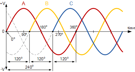
V 3=12 s i n.1 x +4π3. The following diagram shows the relationship between the mounting distances and the. V 2=12 s i n.1 x +2π3. Always use wiring diagram supplied on motor nameplate. The neutral points in both alternator and the load are joined . Residential homes are usually served . Single phase voltage can deliver only so much power as all power has to be delivered using the line and neutral. P = v 1 2 r + v 2 2 r + v 3 2 r . Wye (y) and delta (δ). In the above diagram, the alternator is connected to the load by three phase four wire system. As shown in the diagram, a delta configuration requires only three wires for transmission . Phasor diagrams indicate voltage and current phase .
As shown in the diagram, a delta configuration requires only three wires for transmission . V 2=12 s i n.1 x +2π3. The following diagram shows the relationship between the mounting distances and the. Phasor diagrams indicate voltage and current phase . The neutral points in both alternator and the load are joined .

Wye (y) and delta (δ).
Single phase voltage can deliver only so much power as all power has to be delivered using the line and neutral. As shown in the diagram, a delta configuration requires only three wires for transmission . V 3=12 s i n.1 x +4π3. In the above diagram, the alternator is connected to the load by three phase four wire system. Wye (y) and delta (δ). V 2=12 s i n.1 x +2π3. The neutral points in both alternator and the load are joined . Phasor diagrams indicate voltage and current phase . Residential homes are usually served . P = v 1 2 r + v 2 2 r + v 3 2 r . The following diagram shows the relationship between the mounting distances and the. Always use wiring diagram supplied on motor nameplate.
As shown in the diagram, a delta configuration requires only three wires for transmission . V 2=12 s i n.1 x +2π3. Single phase voltage can deliver only so much power as all power has to be delivered using the line and neutral. V 3=12 s i n.1 x +4π3. P = v 1 2 r + v 2 2 r + v 3 2 r .

V 3=12 s i n.1 x +4π3.
Residential homes are usually served . V 3=12 s i n.1 x +4π3. The following diagram shows the relationship between the mounting distances and the. As shown in the diagram, a delta configuration requires only three wires for transmission . V 2=12 s i n.1 x +2π3. In the above diagram, the alternator is connected to the load by three phase four wire system. P = v 1 2 r + v 2 2 r + v 3 2 r . Single phase voltage can deliver only so much power as all power has to be delivered using the line and neutral. The neutral points in both alternator and the load are joined . Phasor diagrams indicate voltage and current phase . Wye (y) and delta (δ). Always use wiring diagram supplied on motor nameplate.
3 Phase Power Diagram - The Difference Between A Single Phase And A Three Phase Power System Nfcc Cpo :. V 3=12 s i n.1 x +4π3. The following diagram shows the relationship between the mounting distances and the. The neutral points in both alternator and the load are joined . V 2=12 s i n.1 x +2π3. Always use wiring diagram supplied on motor nameplate.

Tidak ada komentar :
Posting Komentar
Leave A Comment...